Hello everyone, nice to meet you all!
My name is Claudio de Vincenzi and I am from Brazil
(my grandparents came from Italy at beggining of the 1900´s).
This is my first post at wellenkino.de forum/community and I was just accepted as a new member. Thank you for acceping me!
I´m not fluent in german, so I apologize for posting this in english. Hope this is not a problem.
Let me recall what I have done until now (I may have forgotten some detail....)
Recently I acquired a Rohde & Schwarz Polyskop III type SWOB with no warranties. Would like to restore the set to is former glory. I am starting a collection of old test sets and instruments and having some difficulties in finding service manuals. For the SWOB 3 the only thing I was able to found up to now was this -
http://www.classicbroadcast.de/download ... _SWOB3.pdf and it seems to be more of an advertise brochure and very useful to understand the overall functions of the set, but not suited for maintenance.
So, I may need some help with that. And any help from you is very welcome!
Thanks in advance!
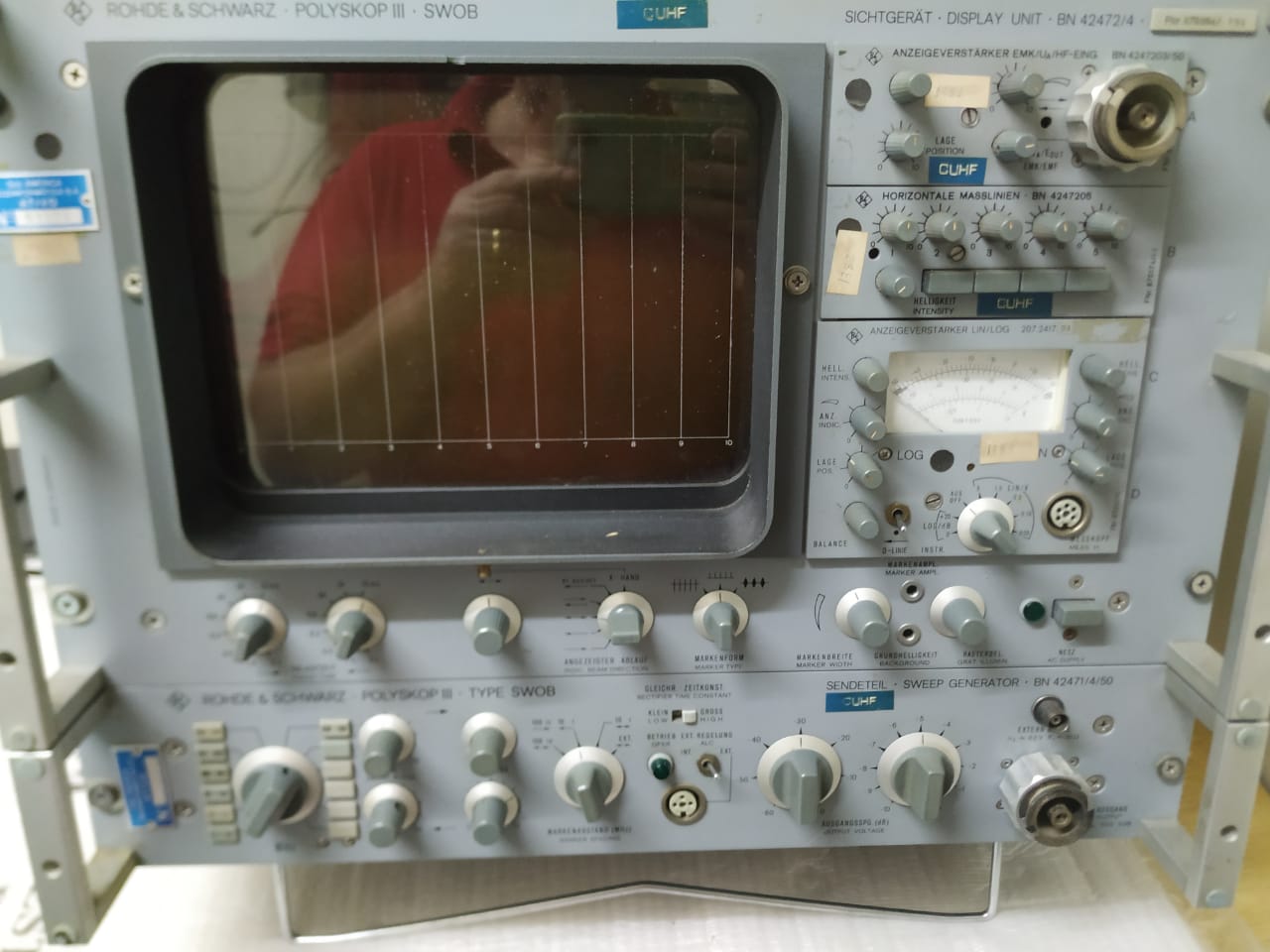
- R&S Polyskop SWOB 3 07-23 at 22.30.28 (5).jpeg (102.82 KiB) 11727 mal betrachtet
Initial Diagnosis
-------------------
The set is built using 2 main modules:
- display module (42472/4)
- sender/generator module (42471/4)
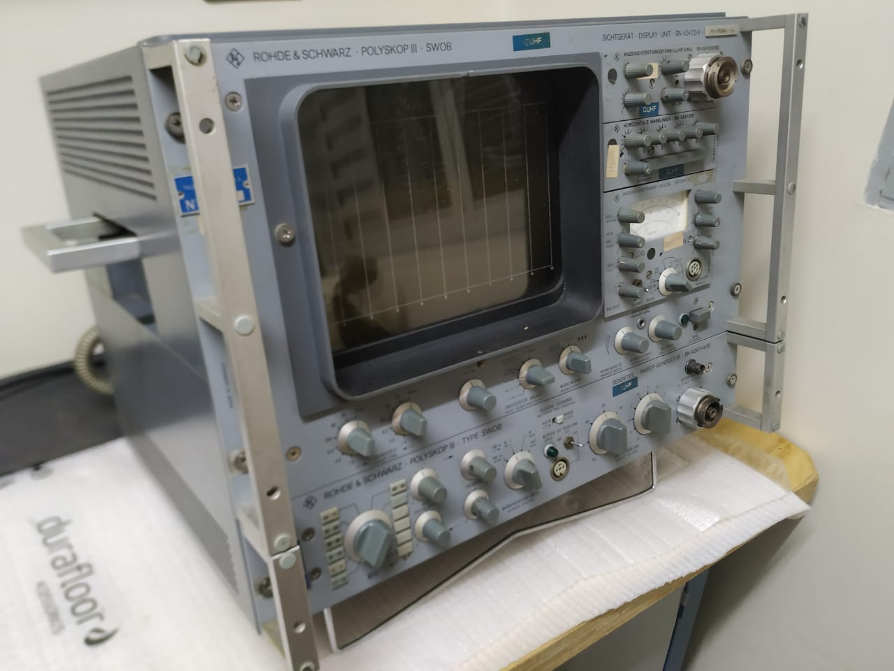
- R&S Polyskop SWOB 3 07-23 at 22.30.28 (4).jpeg (87.6 KiB) 11727 mal betrachtet
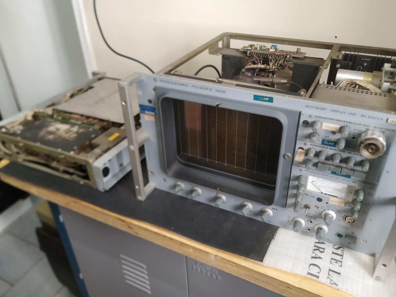
- R&S Polyskop SWOB 3 07-23 at 22.30.32 (1).jpeg (134.17 KiB) 11727 mal betrachtet
These 2 modules are back connected with a short cable and 30 pin connectors.
The set is powering up and showing traces in the CRT.
The display module (42472/4) has CRT HV, focus and bias running ok.
The horizontal timing sets seems to be working ok - I can control X-axis deflection - the time base/frequency - and the CRT displays the dots moving left-right at different speeds.
The 2 input plug-in modules seems ok (42472-203 demod input plug-in and 207-4017-03 lin/log input plug-in).
The dots bright intensity, input gain and Y-positioning controls seems to be working fine.
Unfortunatelly the frequency generator (42471/4 sender module) was stuck. The sweep width control seemed not to be working and no frequency sweep was actually happening.
Fortunatelly, all VCO oscillator cards seems to be ok. I am able to observe their signals (although they seemed dirty and unstable) at the
the RF output plug.
The RF output attenuator seems to be fine too.
After some internet search, I found that
radiomuseum.org had some schematic pages of it available for download. Unfortunatelly, there are no info about what each image contains and also the number of permited downloads is limited at 3 pages per month. And then, I found the wellenkino forum page and am glad to know that you have been discussing about this apparatus for some time.
I would like to ask if you mind in sharing ideas and the service manual pages and schematics with me and help me in fixing the set.
Diagnosis / Progress 1
---------------------------
After many hours studying the 42471/4 sender module hardware/boards/wires/cables I was somehow able to find the following about whats in it:
- VCO (voltage controlled oscillator) frequency cards inside the big metal shield;
- RF Output attenuator (mechanical, a real jewel!);
- Marker generators, inside another metal shield connected to the RF output attenuator
- Negative power supply regulator card (42471-3.11) and filter capacitors;
- Positive ~+160v doubler power supply (no board) with 2 diodes, 2x 47uf capacitors
- Other auxiliary card/boards:
Board Board Function
----------- -------------------------------------------------------------------------------------------------------
42471-10 Part of Frequency Control - send the sawtooth signal to sweep frequency on the VCO cards
42471-11 Not sure what are the functions of that board
42471-12 Seems to be some kind of automatic level control
42471-17 A lot of BF244 FETs, 3 BC108s and some resistors. Probably some kind of electronic switch.
I draw by hand the schematics of 42471-10 and was able to figure out that it sends variable DC signals inside de metal box shield where the oscillators cards reside. It has BF178 transistors that control DC voltages sent to the VCOs. I concluded that this is part of the frequency control. One thing I noticed was that transistor T5 (emitter follower) had positive base voltage but nothing was happening at the emitter. I removed it and tested: it was dead. I replaced it with a BF258 and... nothing, the oscillators continued not wobbling. But now, the emitter was following the base and at the RF output the frequency was more stable and I could control it using the front panel knob.
Diagnosis / Progress 2
---------------------------
I followed if a sawtooth wave was present on the display unit connector. I found low frequency square and sawtooth waves on some pins. They had the same period/frequency set at the Sweep Time controls at the display front panel. But, the same signals were not arriving at the oscillator control board. Opened the cable connectors and tested pin-by-pin for continuity.
For my surprise, there were 2 broken wires at the pin welds. I reconnected them and the cable was now ok. Turned the set on and now the sawtooth wave was arriving at 42471-10 transistor T5 base and being sent to the VCOs. The frequency began wobbling and the sweep width and frequency controls are now working.
Diagnosis / Progress 3
---------------------------
Using an oscilloscope I found that the RF output signal was somehow yet unstable. I was not sure what was happening. The center frequency, even when sweep was turned off, was wobbling in a frequency higher than de horizontal X deflection frequency. I was able to measure that it was wobbling at 120hz, so I suspected that there was a problem with the DC power supply. I used the oscilloscope to measure the PS DC Output Ripple and it was high in the +160V DC supply. More than 20vPP @120hz. And the frequency control board uses that DC supply. I checked the 2x 47uf capacitores in the doubler rectifier of that PS and they seemed not very bad, altough ESR was at ~2 ohms. I added 2 more capacitors in parallel with them and the ripple went down to about 3Vpp. Not the ideal, but better than before. The RF signal then became much more stable than before. So I thought that this issue was solved. Unfortunatelly, it was not.
I began checking the frequency marker generator visual effects and was able to find the markers on the display screen. Dots and lines. Applying a sweep low width causes a zoom-like effect on the marks. When the marks where more separated, they were visibly wagging on the screen, horizontally. Again, this seemed that DC ripple was still a problem.
The frequency marker modules shield was opened and I found that the +160V DC was being used by that circuit. There is a 50V zener diode to reduce the voltage there for some uses, but both +160V and +50v ared used. I added anonther 47uf capacitor in parallel with the zener diode and then the frequency markers began to be more stable than before. But not enough.
I finally added a DC smoother transistor (a 2SC1569 with a 47uF base-to-ground) in series with the +160V power supply output. The ripple went down to less than 100mV and then, finally, both the RF frequency and the frequency marks were now almost rock solid (LOL).
Next Steps
------------------
My next step is to check if the sender is 100% working fine. I have many doubts about the frequencies and sweep alignment and about the function of the other auxiliary cards 42471-11 and 42471-12 .
What I would need
------------------------------
My major concern now is to make the the RF sender unit reliable and working fine. After that, will check the display unit and find if it need some work or not.
- If you have the schematics of the 42471-10, -11, -12 and -17 boards it would be great to have them in order to understand the whole thing.
- If you have the service manual pages related to the alignment/check of the 42471 sender unit it would be great. I dont know about the correct procedure for it and there are a lot of trimpots inside the module.
- If you have the schematics for the 42471 marker generator boards , it would be great to have it (not because it is not working, but because I´m very curious to understand how they designed it in 1970).
Again, any help is very welcome!
Claudio